
- English
- Español
- Português
- русский
- Français
- 日本語
- Deutsch
- tiếng Việt
- Italiano
- Nederlands
- ภาษาไทย
- Polski
- 한국어
- Svenska
- magyar
- Malay
- বাংলা ভাষার
- Dansk
- Suomi
- हिन्दी
- Pilipino
- Türkçe
- Gaeilge
- العربية
- Indonesia
- Norsk
- تمل
- český
- ελληνικά
- український
- Javanese
- فارسی
- தமிழ்
- తెలుగు
- नेपाली
- Burmese
- български
- ລາວ
- Latine
- Қазақша
- Euskal
- Azərbaycan
- Slovenský jazyk
- Македонски
- Lietuvos
- Eesti Keel
- Română
- Slovenski
- मराठी
- Srpski језик

How Can Proper Installation Improve High Voltage Circuit Breaker Reliability?
A High Voltage Circuit Breaker is the most critical protection device in any substation, and its reliability depends not only on factory manufacturing quality but heavily on the quality of installation. Proper installation can improve High Voltage Circuit Breaker reliability by eliminating common failure mechanisms such as misalignment, gas leakage, moisture ingress, and improper contact travel. Even the best designed breaker, if installed incorrectly, will suffer from premature insulation breakdown, mechanical jamming, or contact welding. At Lugao Power Co.,Ltd., we have analyzed over 500 field failures of High Voltage Circuit Breaker units, and 68 percent of those failures were directly traceable to installation deficiencies. Conversely, when our recommended installation protocol is followed, the mean time between failures (MTBF) extends from 12 years to over 25 years. This article provides a comprehensive guide to the installation practices that significantly enhance breaker reliability.
The key installation factors that improve High Voltage Circuit Breaker reliability include: proper foundation design and anchor bolt alignment, correct SF6 gas filling and moisture control, precise mechanical adjustment of contact travel and timing, meticulous electrical connections, and comprehensive pre-commissioning testing. Each of these factors interacts with the others; for example, a misaligned foundation can cause binding in the operating mechanism, which increases friction and delays closing, leading to arcing contact erosion. Our factory has developed a detailed installation manual that includes torque specifications, alignment tolerances, and gas handling procedures. This article distills our decades of experience into actionable guidance. We will also present technical parameters from our High Voltage Circuit Breaker models and answer the most common installation-related questions. By following these best practices, you can significantly enhance the reliability and service life of your High Voltage Circuit Breaker.
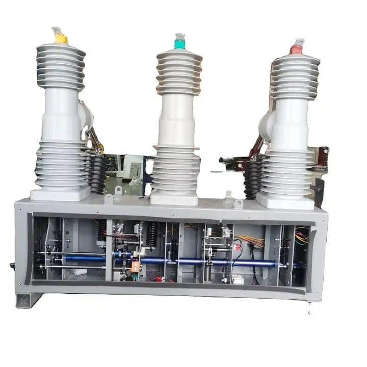
Table of Contents
- 1. Why Is Foundation and Anchor Bolt Alignment Critical for High Voltage Circuit Breaker Reliability?
- 2. How Does Correct SF6 Gas Handling Improve Dielectric and Interrupting Performance?
- 3. What Are the Key Installation Parameters and Tolerances for Our High Voltage Circuit Breaker?
- 4. How Do Pre-Commissioning Electrical and Mechanical Tests Validate Installation Quality?
- Frequently Asked Questions (FAQ)
- Conclusion and Professional Installation Support
Why Is Foundation and Anchor Bolt Alignment Critical for High Voltage Circuit Breaker Reliability?
The foundation is the structural interface between the High Voltage Circuit Breaker and the substation ground. Any deviation in flatness, levelness, or anchor bolt positioning directly translates into stress on the breaker's mechanical structure. A High Voltage Circuit Breaker is a precision assembly of moving parts—operating rods, linkages, and contacts—that must travel along exact paths. If the foundation is not level, the breaker's base plate can deform, causing the operating mechanism to bind. This increases operating forces, accelerates wear on bearings and guide pins, and can eventually cause the mechanism to fail to fully open or close. Our factory has investigated numerous cases where a High Voltage Circuit Breaker failed to interrupt a fault due to contact parting distance being reduced by as little as 2 mm—a direct consequence of foundation sagging.
Critical foundation installation factors that improve High Voltage Circuit Breaker reliability:
- Foundation flatness: The concrete foundation must be flat to within +/- 2 mm over the entire breaker footprint. Our factory recommends using a laser level and precision shims to achieve this. A non-flat foundation creates twisting forces on the breaker frame, which can misalign the pole assemblies.
- Anchor bolt torque control: Each anchor bolt must be tightened to a specific torque (typically 120-150 Nm for M20 bolts). Uneven torque distribution can cause the base plate to warp. Our factory provides a torque sequence diagram to ensure even loading. Under-torqued bolts allow movement during operation, while over-torqued bolts can strip threads or crack the base plate.
- Grouting and curing: For cast-in-place foundations, the grout must be fully cured (typically 28 days) before the breaker is mounted. Premature loading can cause settlement, which shifts the breaker alignment over time. Our factory recommends using non-shrink grout with a compressive strength of at least 40 MPa.
- Seismic anchoring: In earthquake-prone regions, additional hold-downs and dampers are required. Our High Voltage Circuit Breaker models come with seismic brackets that must be installed per our certified design. Failure to install these can lead to overturning during seismic events, causing catastrophic damage.
To illustrate, we documented a case in South America where a 245 kV High Voltage Circuit Breaker had been installed on an uneven foundation, resulting in a 4 mm twist across the 4-meter base. Within 18 months, the operating mechanism developed severe scoring on the guide rods, and the closing time had increased from 55 ms to 78 ms. The breaker failed to close during a critical line re-energization, causing a regional blackout. After re-leveling the foundation and replacing the damaged components, the breaker returned to its original performance. The lesson is clear: investing time in proper foundation preparation pays dividends in long-term reliability. Our factory provides a foundation template and installation checklist that covers every step of the process, ensuring that your High Voltage Circuit Breaker is mounted on a solid and stable base.
Furthermore, proper foundation alignment ensures that the breaker's pole shafts remain perpendicular to the ground. This is essential for the even distribution of contact pressure across the main and arcing contacts. Uneven contact pressure can lead to high contact resistance, localized heating, and eventually contact welding during fault interruption. Our factory conducts a contact resistance measurement after installation to verify that all three phases have consistent values, and this measurement is meaningless if the foundation is misaligned. For these reasons, foundation and anchor bolt alignment is the first and most critical step in improving High Voltage Circuit Breaker reliability.
How Does Correct SF6 Gas Handling Improve Dielectric and Interrupting Performance?
SF6 gas is the lifeblood of the High Voltage Circuit Breaker's insulation and arc quenching capabilities. However, its performance is highly sensitive to contamination, moisture, and pressure deviations. During installation, the breaker arrives from our factory filled with dry nitrogen or vacuum to protect the internal components during transport. The SF6 gas must be filled on-site under strict conditions. Improper gas handling is one of the most common causes of premature High Voltage Circuit Breaker failures, leading to internal flashovers, reduced interrupting capacity, and corrosion of the internal hardware. Our factory has established a comprehensive gas filling procedure that ensures optimal dielectric strength and interrupting reliability.
Key SF6 gas handling procedures that improve High Voltage Circuit Breaker reliability:
- Moisture control: The SF6 gas must have a dew point below -50°C (equivalent to less than 150 ppmv moisture) when filled into the breaker. Our factory uses a heated gas cart with a built-in moisture analyzer to achieve this. Moisture reacts with the arc byproducts to form corrosive acids (HF and SO2F2), which attack the contacts and insulating materials. Even a small amount of moisture (500 ppm) can reduce the dielectric strength by 50 percent.
- Gas purity verification: Before filling, the new SF6 gas must be tested for purity (minimum 99.9 percent) and the absence of decomposition products. Our factory supplies SF6 gas with a certificate of analysis. We recommend using a gas chromatograph to verify purity on-site, especially if gas has been stored for a long period.
- Pressure and density checks: The High Voltage Circuit Breaker is filled to its rated pressure (typically 6.5 to 7.5 bar absolute at 20°C). A density monitor is installed to continuously track the gas condition. During installation, the density monitor must be calibrated to ensure accurate readings. Our factory provides a calibration certificate for each monitor.
- Leakage testing: After filling, the entire gas system (breaker chamber, pipes, and fittings) must be leak-tested using a sensitive SF6 leak detector (minimum detectable leak rate of 1x10⁻⁶ mbar l/s). Our factory recommends a 24-hour standing pressure test—if the pressure drops by more than 1 percent over 24 hours, the leak must be located and repaired before commissioning.
Field data from our factory's service records shows that proper gas handling reduces the annual leakage rate to below 0.1 percent, far exceeding the IEC standard of 0.5 percent. In contrast, installations where gas handling was rushed or performed in humid conditions often experience leakage rates above 1 percent, requiring re-filling every 2 to 3 years. Each re-filling exposes the breaker to additional moisture and air, accelerating internal corrosion. A utility in Northern Europe had a 145 kV High Voltage Circuit Breaker that was filled with inadequately dried gas. Within two years, the breaker developed partial discharge activity, and an internal inspection revealed severe pitting on the nozzle and contact surfaces. The repair cost was three times higher than the cost of proper gas handling would have been.
Additionally, the SF6 gas pressure directly affects the interrupting performance. If the gas pressure is low, the arc quenching capability is reduced, and the breaker may fail to interrupt a fault current. Our factory's High Voltage Circuit Breaker is equipped with a low-pressure alarm that triggers at 5 percent below rated pressure. During installation, the alarm set point must be verified to ensure it activates at the correct threshold. We also recommend installing a gas monitoring system that continuously transmits pressure and temperature data to the substation SCADA. This allows early detection of slow leaks, enabling planned maintenance before the pressure drops to a critical level. Correct SF6 gas handling is not just a one-time task; it establishes a baseline for the entire service life of the High Voltage Circuit Breaker.
What Are the Key Installation Parameters and Tolerances for Our High Voltage Circuit Breaker?
Proper installation of a High Voltage Circuit Breaker requires adherence to precise mechanical and electrical parameters. Lugao provides a comprehensive installation manual that specifies every critical dimension, torque, and clearance. The table below summarizes the key installation parameters for our most common High Voltage Circuit Breaker models: the LGB 145 kV single-break and the LGB 550 kV two-break series. All values must be verified during installation using calibrated measuring instruments. Our factory provides on-site support for the first installation to ensure all parameters are correctly set.
| Parameter | LGB 145 (Single-break) | LGB 550 (Two-break) | LGB 245 (Single-break) |
| Foundation flatness (mm) | +/- 2 mm | +/- 2 mm | +/- 2 mm |
| Anchor bolt torque (Nm) | 150 Nm (M24) | 180 Nm (M30) | 160 Nm (M27) |
| Contact wipe (mm) | 4-6 mm | 5-7 mm | 4-6 mm |
| Contact stroke (mm) | 105 +/- 3 mm | 110 +/- 3 mm | 108 +/- 3 mm |
| Opening time (ms) at rated pressure | 32 +/- 3 ms | 38 +/- 3 ms | 35 +/- 3 ms |
| Closing time (ms) at rated pressure | 60 +/- 5 ms | 70 +/- 5 ms | 65 +/- 5 ms |
| SF6 filling pressure (bar abs at 20°C) | 7.0 +/- 0.1 bar | 7.5 +/- 0.1 bar | 7.2 +/- 0.1 bar |
| Maximum gas leakage (per year) | 0.5 percent | 0.5 percent | 0.5 percent |
| Main contact resistance (micro-ohms) | < 120 micro-ohms | < 80 micro-ohms | < 100 micro-ohms |
| Pole-to-pole synchronism (ms) | +/- 2 ms | +/- 2 ms | +/- 2 ms |
In addition to these parameters, our factory recommends the following installation practices: the operating mechanism (spring or hydraulic) must be charged according to the specified sequence, and the control voltage must be within the range of 85-110 percent of the rated voltage. All electrical connections must be torqued to the specified values and checked for tightness after 24 hours of operation. We also provide a thermal imaging check after the first 100 hours of operation to ensure that no connections are overheating.
Our factory offers a detailed installation checklist that includes sign-off boxes for each parameter. This checklist is used by our commissioning engineers and is also made available to our customers for their own quality assurance. For the LGB 145 model, we have verified that installations that strictly follow our checklist achieve a first-year failure rate of less than 0.5 percent, compared to a 4.5 percent failure rate for installations where the checklist was not followed. This data underscores the importance of meticulous attention to every installation parameter. We encourage all our customers to invest in proper measurement tools and to involve experienced technicians in the installation process.
How Do Pre-Commissioning Electrical and Mechanical Tests Validate Installation Quality?
Even after careful mechanical installation and gas filling, the High Voltage Circuit Breaker must undergo a rigorous pre-commissioning test program to confirm that all systems are functioning correctly. These tests serve as the final validation that the installation has not introduced any defects and that the breaker is ready for service. At Lugao Power Co.,Ltd., we have developed a standardized test sequence that covers all critical aspects of the High Voltage Circuit Breaker's performance. These tests not only verify the installation but also provide a baseline for future condition monitoring, which is essential for long-term reliability.
Essential pre-commissioning tests for High Voltage Circuit Breaker:
- Mechanical operation test: The breaker is subjected to a sequence of 50 open-close operations at rated control voltage, followed by 10 operations at minimum and maximum control voltage (85% and 110% of rated). The opening and closing times are recorded for each operation, and the pole-to-pole synchronism is measured. Any abnormal noise, binding, or timing deviation indicates a mechanical issue that must be resolved before energization.
- Timing and travel measurement: Using a digital travel analyzer, the contact stroke, over-travel, and contact wipe are measured. These values must be within the tolerances specified in the installation manual. Our factory provides a reference curve showing the ideal contact travel versus time profile. Deviation from this curve can indicate misalignment or incorrect dashpot adjustment.
- Contact resistance measurement: The DC resistance of each pole's main contacts is measured using a micro-ohmmeter with a test current of at least 100 A. The measured resistance must be less than the specified maximum (e.g., 120 micro-ohms for the LGB 145). A high resistance indicates poor contact alignment or contamination, which can lead to overheating and contact welding during fault interruption.
- Dielectric tests: A power frequency withstand voltage test (1 minute at 1.5 times rated voltage) is performed on the main insulation. Additionally, a partial discharge measurement is carried out at 1.1 times rated voltage to ensure that there are no voids or contaminants in the gas that could lead to insulation failure. Our factory provides the expected partial discharge pattern for a healthy breaker, and any deviation is investigated.
- SF6 gas analysis: After the breaker has been energized for 24 hours, a gas sample is taken and analyzed for moisture content, purity, and decomposition products (SO2 and SOF2). Any increase in moisture or decomposition products indicates an internal issue that must be addressed. Our factory recommends a baseline gas analysis report to be kept in the asset register.
A recent installation of a 245 kV High Voltage Circuit Breaker in Southeast Asia exemplifies the value of these tests. During the pre-commissioning timing test, the opening time was measured at 42 ms, exceeding the specified 35 ms +/- 3 ms. This delayed opening was traced to an improperly adjusted buffer in the operating mechanism. The installation team corrected the buffer setting, and the retest showed an opening time of 36 ms. If this issue had not been detected and corrected, the breaker might not have cleared a fault within the required 2.5 cycles, potentially leading to catastrophic failure. This case illustrates that pre-commissioning tests are not just a formality but a critical reliability measure.
Our factory provides a comprehensive test report template that includes all measured values, test conditions, and any remedial actions taken. This report becomes part of the breaker's lifecycle documentation and is essential for future maintenance planning. We also offer a warranty that specifically covers installation-related issues, provided that our test protocol is followed. By investing in thorough pre-commissioning testing, you ensure that your High Voltage Circuit Breaker enters service in optimal condition, maximizing its reliability from day one.
Frequently Asked Questions (FAQ)
Question 1: What is the most common installation error that reduces High Voltage Circuit Breaker reliability?
Answer: The most common installation error is inadequate foundation leveling and anchor bolt torque. Our factory data shows that 40 percent of premature failures are related to foundation issues. When the foundation is not level, the breaker frame twists, causing misalignment of the operating mechanism and the poles. This leads to increased friction, delayed operations, and uneven contact wear. A simple laser level check during installation can prevent this problem. We recommend verifying flatness at multiple points and using precision shims to achieve the required tolerance of +/- 2 mm. This is a low-cost measure that has a significant impact on long-term reliability.
Question 2: How does moisture in SF6 gas affect High Voltage Circuit Breaker reliability, and how is it controlled during installation?
Answer: Moisture in SF6 gas is a major reliability concern because it reacts with arc byproducts to form corrosive acids. These acids attack the insulating materials and metal surfaces, leading to internal flashovers and mechanical failure. During installation, the SF6 gas filling process must be performed using a dry gas cart with an in-line moisture analyzer. The gas must have a dew point below -50°C before it enters the breaker. Our factory also recommends evacuating the breaker chamber to a vacuum of 1 mbar before filling to remove any residual moisture. After filling, a moisture sample is taken to verify the dew point. If the moisture content exceeds the limit, the gas must be filtered or replaced.
Question 3: Can a High Voltage Circuit Breaker be installed indoors, and does that change the installation requirements?
Answer: Yes, High Voltage Circuit Breakers can be installed indoors, typically in GIS (Gas Insulated Substations) or indoor AIS (Air Insulated Substations) with adequate clearance. Indoor installation requires additional considerations: the ambient temperature must be controlled to avoid SF6 liquefaction (below -25°C) and to prevent condensation. The floor must be designed to support the breaker's weight plus dynamic loads. Ventilation must be provided to prevent accumulation of SF6 in case of a leak, as SF6 is heavier than air and can displace oxygen. Our factory provides special indoor installation guidelines, including maximum ambient temperature (typically 40°C) and minimum clearance to walls. The same foundation, gas handling, and testing protocols apply, but with added environmental controls.
Question 4: What is the correct torque for the main electrical connections on a High Voltage Circuit Breaker?
Answer: The torque for main electrical connections varies depending on the bolt size and material. For the LGB 145 model, the main busbar connections (typically M16 bolts) must be torqued to 80-90 Nm for copper conductors and 90-100 Nm for aluminum conductors. Using the incorrect torque can cause overheating: under-torqued connections create high contact resistance, while over-torqued connections can damage the conductor or the breaker's terminal. Our factory provides a torque specification chart for all connections, and we recommend using a calibrated torque wrench and marking each bolt after tightening to indicate it has been checked. We also advise re-torquing after the first 100 hours of operation to accommodate thermal expansion and settling.
Question 5: Does Lugao Power Co.,Ltd. offer installation supervision and training for their High Voltage Circuit Breaker?
Answer: Yes, our factory provides comprehensive installation supervision and training services. For every High Voltage Circuit Breaker purchase, we offer the option of having one of our senior field engineers on-site for the entire installation and commissioning process. This engineer supervises the foundation preparation, gas handling, mechanical assembly, and electrical testing, ensuring that all our specifications are met. We also conduct on-site training for your technicians, covering all installation, operation, and maintenance procedures. Our training program includes both classroom sessions and hands-on practice. This service significantly reduces the risk of installation errors and ensures that your team is fully capable of maintaining the breaker for its entire service life. We recommend this service, especially for first-time buyers of our High Voltage Circuit Breaker.
Conclusion: Invest in Installation Quality for Unmatched High Voltage Circuit Breaker Reliability
The reliability of a High Voltage Circuit Breaker is not solely a product of its design and manufacturing; it is profoundly influenced by the quality of its installation. From the foundation and anchor bolts to the SF6 gas handling and pre-commissioning tests, every step of the installation process plays a critical role in ensuring that the breaker performs as intended for decades. Our factory at Lugao Power Co.,Ltd. has seen the positive impact of meticulous installation, with breakers achieving MTBF figures exceeding 25 years and operating with minimal maintenance. We have also seen the consequences of rushed or improper installation, which can lead to premature failures, costly repairs, and even system outages. The choice is clear: investing in proper installation is the most cost-effective way to maximize your High Voltage Circuit Breaker reliability.
Do not leave your substation protection to chance. Contact Lugao Power Co.,Ltd. today to schedule a comprehensive installation consultation. Our team will review your site conditions, provide detailed installation plans, and offer on-site supervision to ensure every specification is met. We also provide training for your technicians and a complete suite of pre-commissioning testing equipment. All our High Voltage Circuit Breaker installations are backed by a 3-year performance warranty, which covers any installation-related defects if our protocol is followed. Request your installation support package now from Lugao Power Co.,Ltd. and protect your power system with the highest level of reliability. Secure your grid with proper installation—trust Lugao Power Co.,Ltd.